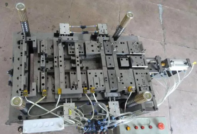
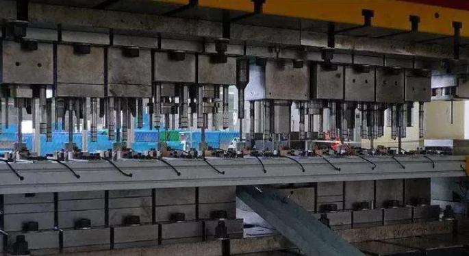
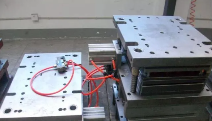
(4) Complex structure: with the diversification and individualization of social needs and the wide application of many new materials and processes, the structural form of modern mold requirements are increasingly complex.
In the production of molds and dies, the parts that cause damage to the molds and dies are often the edge of the die, the damage to the edge of the die directly leads to make the stamping parts of the burr is too large, the parts of the high rate of rework, increase production costs. The damage to the edge of the die is only a small part of the entire mold, especially in the blanking of metal parts, blanking die is often damaged in the small convex die, in the large mold blanking die in the small convex die, often damaged to a different extent. Therefore, in some cases, as long as the improvement of blanking die in the small convex die can greatly improve the life of the mold, the following, we will take the small convex die as an example, to explore how to apply the large mold on the small parts and extend its service life:
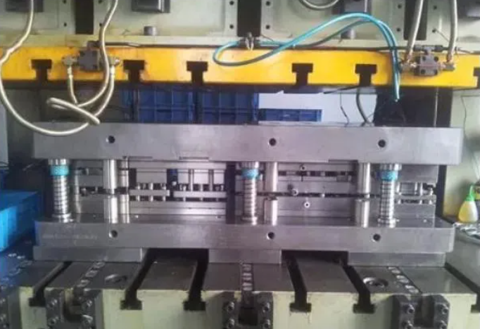
1. Keep the position of mold parts stable
When the mold is working, all the parts on the mold are required to maintain a stable design position. The mold processing clearance, including the uniform fit of the convex and concave die gaps for blanking, bending, forming, etc., is an important aspect of controlling the relative position. To blanking die, for example, if the convex and concave die with uneven clearance, around the convex die shear edge will produce a balanced load, resulting in uneven wear, in this case, the total load forcing the convex die offset, so that the convex die fixing plate with the hole gradually larger, the production of the edge of the stamping parts will appear a larger burr, and serious will lead to the convex die crack.
Therefore, when designing the mold, the force generated by the mold at work should be fully considered. First analyze the vertical punching force, then analyze whether the sub-vertical force will produce lateral thrust, and whether the lateral thrust will affect the relative position of the parts. In the production mold, not only punching will produce lateral thrust, bending, stretching are the same lateral thrust, asymmetric workpiece forming and stretching, as well as the use of cam slanting wedge action of the mold, will produce large lateral thrust. For this reason, measures must be taken to prevent lateral thrust from affecting the design positioning. In addition, the size, accuracy and number of guide bushings, as well as the size and position of pins and screws in the fastening module, are important aspects of maintaining the relative position, and need to be designed and arranged appropriately. The generation of lateral thrust is also related to the technology of mold manufacturing and the precision of the press. For this reason, when designing the mold, the standard size should start from the same part, which is conducive to ensuring the relative position of the mold working part and the guiding part, and the standard size of the coordinate type is conducive to the positioning and processing of the machine tool to reduce manual errors.
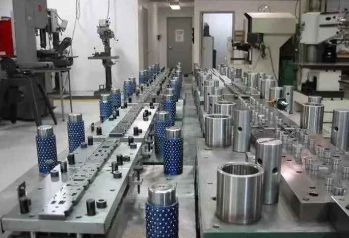
2. Material control in stamping
Throughout the stamping process, how to ensure the position and support of the material being stamped should be considered in terms of the stress and strain of the material, as well as the constraint of the material. There are several ways to restrain the material as follows:
2.1 Increase the elastic unloading plate with guide post. Install guide posts and guide bushings on the upper and lower mold seats of the mold, and add compression load stresses to the material;
2.2 The use of guide pins for the precise positioning of the material in multi-station molds, the distribution and number of guide pins should be sufficient so that the material and the workpiece can be correctly positioned through the entire mold, and the distribution of the guide pins should be where the material or the workpiece is least skewed, so as to obtain the correct guiding over the entire length of the mold. In the process design should be punched in the first station when the guide hole, such as the workpiece does not have a hole can be utilized, in the waste side of the material or the need to punch off the location of the set of process holes, hole diameter as large as possible;
2.3 The use of equipment on the anti-movement pins to resist punching notches and one-sided bending processing, such as the side stress generated by the mold;
2.4 The small die should be placed in such a way that it is not subject to premature wear caused by the punching stresses of the large die;
2.5 The material to be punched should be properly supported to prevent wrinkling and other deformations, and the various stations in the progressive die must be designed at the same feeding height, and a material lifter should be provided to lift the filler to the same feeding height. For the process of stretching or molding, it should be considered whether to use upward or downward molding, which is conducive to the feeding of strips.
2.6 In the progressive die, determine the shape and size of the blank required for stretching or forming process, the free flow of material should be considered at the same time, according to the shape of the formed workpiece, the cut-off process of the workpiece from the filler should be arranged before the last forming process.
3. Vibration control during operation
In designing a convex die, due consideration should be given to the vibration produced when the die enters the material and when the material breaks, and the vibration should be transmitted through the end of the die to the shank of the die and finally dispersed to the die as a whole. Any blockage of the impact force will inevitably cause the rupture of the die. In order to stabilize the small die against vibration, the area of the shank of the die should be twice the area of the end and the area of the head should be four times the area of the end. The length of the end of the convex mold should also be taken into account. When unguided tool steel is used, the length of the end should not be more than 2.5 times the diameter of the end, and for HSS convex molds, this value can be increased to 4 times. In order that the vibration wave can be smoothly transmitted from the end of the convex die through the convex die fixing plate and finally to the whole die, the connection between the end of the convex die and the shank, as well as between the shank and the head, are suitably circularly coupled. In some cases, when the effective portion of the convex die is intentionally lengthened in order to extend the life of the die, measures should be taken to prevent skewing or twisting due to vibration of the convex die.
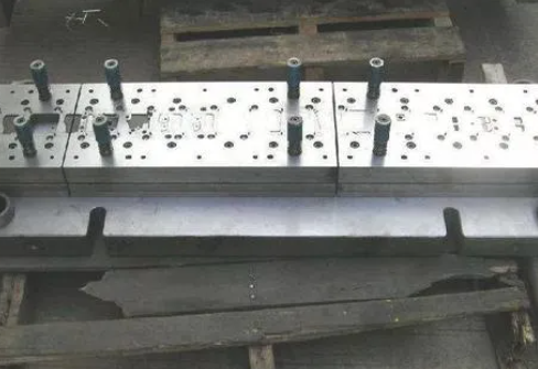
4. Waste control of manufactured parts
In production practice, there are two main problems arising from scrap, one is the rise of scrap, and the other is the blockage in the scrap hole. Waste rise is due to the gap is too large, punching the role of the material on the tensile force makes the stamped part than the mold hole is small, but also due to the convex die bottom surface and waste material produced by the vacuum adsorption phenomenon caused; waste blocking is due to the gap is too small, punching the role of the material on the compression force makes the stamped part than the hole in the concave mold is large or due to the concave die hole wall roughness and aperture diameter of inappropriate waste caused by the main reason for the rise and blocking.
4.1 Methods for preventing scrap from rising:
4.1.1 By means of spikes;
4.1.2 Method of blowing off with air;
4.1.3 Creating a local vacuum at the bottom of the concave mold to draw the scrap down;
4.1.4 Making a 1° bevel on the head of a small convex mold.
4.1.5 Hollowing out the center of the convex die to reduce the contact area and prevent the scrap from sticking to the bottom of the convex die.
4.1.6 Give a shear angle on the convex die and use the rebound force of the punch to induce the punch to come off;
4.2 Methods of preventing clogging of fertilizers:
4.2.1 The straight-edged portion of the concave die must not hold more than six punches;
4.2.2 The lower end of the straight-edged portion should be provided with a drop slope;
4.2.3 Inclined holes should be made in the pad to prevent the scrap from stacking into cylindrical shape and making it fall off piece by piece;
4.2.4 Add large drop holes on the mold base to prevent clogging.
5. Wear control
It has been proved that 2/3 of the wear of the small convex die in the mold is the wear of the convex die from the material to be punched out from which the wear is generated and affects the size of the punched holes. Generally, the convex die wears faster than the concave die, and there is no simple formula or method to determine a reasonable clearance value. It can only be obtained by experimentation. Experimental studies have proved that increasing the clearance value used in the past by 2 Times, will greatly improve the life of the mold 2-3 times, while the quality of the stamped part has little or no effect. In addition, whether the convex die is guided or not, and whether the material to be processed is pressed or not, have a greater relationship to the wear of the convex die. Through the test, the convex die without guide and the concave die and the unloading plate to keep guiding the occasion comparison, its life has obvious difference, the convex die guide 6-7 times higher. The material being processed with or without pressure parts, the wear of each part of the convex and concave die is different, concave die surface wear can be reduced due to the pressure plate, but the wear of the convex die end face instead of increasing. This is due to the fact that the press plate holds the peripheral plates in place. The elongation of the machined material in the direction of the guide has to come from the
The elongation of the material to be processed in the guiding direction has to be generated from the inside of the shearing section, thus increasing the sliding of the end face of the convex die against the material to be processed. Wear of the die surface is reduced by suppressing the movement of the material above the die because of the clamping plate, and wear of the side of the convex die is reduced by the clamping plate because the elastic recovery of the punched edge material is reduced by the clamping plate, which reduces the pressure on the side of the convex die. Another way to reduce wear is to choose the right steel for the mold. The steel selection of the mold can not only consider easy processing and heat treatment, at the same time should be based on the characteristics of the material to be processed as well as the molding process to choose. Should be more from the convex and concave mold edge shape to consider. In a mold is not limited to use a kind of steel, according to the need to choose a variety of materials, so that the whole mold wear and tear to achieve a balance.
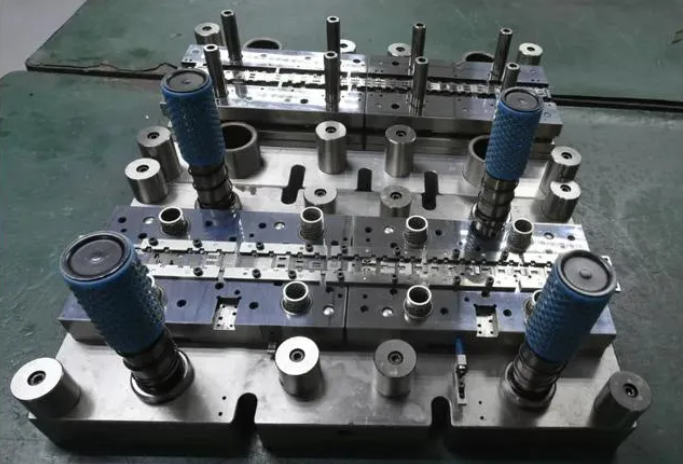
6. Control of mold load
The load center of the die is required to be basically the same as the pressure center of the press in the front, back, left and right directions. Left and right load should be limited to within 1/10 of the degree of difference, foreign multi-position progressive die in the design process of each station to calculate the tonnage of the punching pressure, and require the load center to check whether it is close to the center of the press slider. If the load center shift is too large under certain circumstances, a load leveling block must be provided on the die to reduce the amount of shift caused by the unbalanced load. The unloading spring must be set at the location where the unloading is the center of the load to eliminate the unloading from creating skew. We know from the above analysis, if the design of the mold to fully consider the above six aspects, you can greatly improve the service life of the mold, reduce the cost of maintenance of the mold, reduce the economic burden of enterprises.
If you have mold customization needs,please contact us!
