Resources
Multi-Shot Tooling Approaches Eliminate Part Welding
Three new multi-shot tooling concepts that involve stationary cavities and indexing cores use injection overmolding to eliminate post-mold welding operations and improve part quality and productivity while reducing scrap. One approach brings part assembly into the press. Another produces thick-wall parts in less time by building up the part in the mold from successive layers of material. And a third approach overmolds one half of a complex hollow part onto another half. These developments come from French moldmakers JP Grosfilley SAS (Oyonnax) and Georges Pernoud (Martignat), which formed a consortium called AGP Group together with a third French moldmaker, Collom. Grosfilley and Pernoud exhibited at last year’s NPE and Fakuma shows in Chicago and Germany.
 |
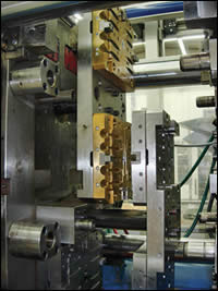
| In-mold assembly (IMA) tool from Grosfilley includes top and bottom rotating plates, which meet in the center to produce two-component overmolded parts. |
IN-MOLD ASSEMBLY ADVANCES
Moulages Industriels Du Haut Bugey (M.I.H.B.), a French firm specializing in multi-shot injection molding and assembly, partnered with Grosfilley (grosfilley.fr) to develop a turnkey system to produce a spray nozzle for car windshield wipers. M.I.H.B. in Oyonnax molds 2 million of these parts annually. “The wiper was previously made out of two part shells molded on separate machines and then ultrasonically welded,” says Sebastian Jacquand, technical sales manager at M.I.H.B (mihb.com). The nozzle has five small spray holes, which can be compromised during welding. “Part quality was based on optimal performance from three different operations and that was hard to maintain. Our new in-mold assembly (IMA) approach uses one tool, one press, one process for lower overall investment and a complete part from the mold.”
At the heart of the IMA process is a special tool design from Grosfilley that features two indexing plates in one mold. This differ from typical 2K molding where there is one indexing device that moves an intermediate part from one fixed set of cavities to another. Grosfilley divides the mold into three sections—upper, middle, and lower levels. One half of the part is molded onto the rotating cores in the upper half of the tool on one platen, while the other half of the part is molded onto a different rotating core plate on the lower tool half on the other platen. The middle section of the tool is accessed by both indexing plates. “The indexing plates rotate 180° to a common overlapping area in the center of the mold. The two part halves are brought together at that center section and can be assembled by overmolding a seal,” says Grosfilley sales manager, Claude Montegani. The parts molded in the upper index plate rotate down to the center area, while the parts molded in the lower index plate rotate up to the same center area, so the mating parts end up face to face. When the mold closes, the second injection unit molds a seal around both parts in the middle section of the mold, while first-shot injection occurs in the upper and lower levels of the mold. Each rotating index plate is driven independently by a high-torque servo motor that rotates the plate 180°. The plates rotate at the same time.
Grosfilley built an 8+8+8 mold, which is installed on a 220-ton Billion machine with two injection units. The left side of the windshield spray nozzle is molded in eight cavities in the upper section of the mold, while the mating half is molded in eight cavities on the lower index plate. Both halves are molded at the same time with the primary injection unit. When the mold opens, both indexing plates extend from the mold base and rotate 180°. A robot removes eight finished parts and the sprue and performs a quality check by blowing air through each part to check the orientation of each spray hole using air through the part to measure air spot deviation. The parts are then placed on a conveyor. The cycle time is 28 sec. The previous process was much longer. “It took one minute for the whole process, from injection to welding” says Jacquand.
MOLD THICK PARTS IN LAYERS
Grosfilley also combines overmolding with a special indexing tool in a new way to make thick parts on smaller presses in shorter cycles. Its Multilayer concept produces thick parts by overmolding successive thin layers of the same polymer in the same mold. The layers can be 0.8 to 5 mm thick. This produces a part that can be free of weld lines and stresses, says Montegani.
An indexing plate moves the parts from station to station. “The mold and the process have to be fine-tuned and the machine parameters are critical. We had to work on how to index quickly while minimizing shrinkage, and how to inject slowly to avoid weld lines.” Temperature control of the mold is critical for this process.
The multilayer process has been used to mold non-cosmetic parts such as hand tools, but Grosfilley also targets thick cosmetic parts. The process reportedly allows combinations of different colors or labels inserted between layers. One application is a ball for Pétanque, a form of boules or the Italian game of bocce. The usual 8-cm-diam. metal ball was replaced by PC or PMMA. The Grosfilley process first molds a small ball and then overmolds four successive layers of material in sequential molding stations.
 |
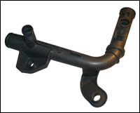
| Multitube process from Georges Pernoud produces complex hollow parts in two halves and then overmolds a seal to join them. It saves post-mold welding for auto cooling pipes and air ducts. |
WELDING BY OVERMOLDING
Georges Pernoud (pernoud.com) developed the Multitube tool concept, which eliminates welding of complex hollow parts like automotive water pipes and air ducts and provides weight and cycle-time savings. Pernoud, represented by MI Integration in Sherbrooke, QC (mi-integration.com) specializes in tools for under-the-hood automotive parts such as intake manifolds and cylinder-head covers, as well as fuel filler doors and rear-view mirrors. “The designs of many parts are so tricky that even a conventional mold with several retractable or rotating cores can’t avoid the welding step, as well as longer cycle time and heavier parts. A conventional process takes seven steps, molding two part halves in a family mold. The halves are then transferred by robot to a vibration welding station.
The Multitube method applied to automotive pipes and ducts reduces the process to four steps and achieves a 15% weight savings and cycle-time savings of 0.5 to 2 sec. In a two-cavity family tool, one half of the part is molded in one cavity and then is transferred by robot to the second cavity, where the other half is overmolded. Montegani says Multitube can be used with a rotary plate instead of a robot. He says the rotary plate provides better shrinkage control, because the part remains on the core during rotation from cavity to cavity.
- What affects injection mold machining accuracy and productivity?
- Shenzhen top five mold manufacturers: how plastic products are processed and produced?
- Shenzhen Ideal Vowin mold manufacturer: how to effectively improve the precision of mold processing?
- Chrome plating, a process that makes cars stylish
- Six injection molding processing technologies for home appliance plastic products
- Advantages and disadvantages of injection molding vs blow molding
- What is automotive hot stamping and molding technology?
- What is the difference between a hot runner and a cold runner in the mold?
- Automotive stamping die in large, precision and other areas of progress is obvious, the rapid development of plastic and rubber molds
- The top ten problems that are likely to occur in the mold testing process


