

Resources
Why is FEA of plastic parts so often wrong?
We’ve all seen the presentations, a series of impressive-looking color plots showing a finite element mesh, with professional-looking color gradients representing peak stresses.
Heads nod knowingly, and the “experts” conclude that the part is well designed and ready for tooling release. Drawings are released, and injection molds are built with all stakeholders confident that the part is well within design loads. Fast-forward four months: Tool verification is complete, first articles are in and looking good, and it’s time for the first load test of a molded part.
And the part fails.
Unfortunately, this scenario is all too common in product development, despite the organizational awareness of the value of finite element analysis (FEA) for plastic parts, and despite the near-ubiquitous presence of high-end analysis software in design organizations.
The analysis and computer simulation of plastic parts is more often done wrong than right.
Origins of FEA tools
Some of the reasons for these rather consistently poor results in structural analysis of plastics go back to the origins and early use of FEA software. FEA codes were largely developed for the aerospace industry and were concerned predominantly with metals. Metals have rather simplistic, easy-to-predict behavior at or below the yield stress of the material, and the dirty little secret of FEA for metal structures is that there is very little use for predicting results above the yield limit, as that means (for the most part) the structure has failed.
And no one wants a broken airplane part, so the majority of the analysis is centered around linear elastic material models and predicting structural performance in the elastic range of metals—which means in the vicinity of 2%-5% strain.
|
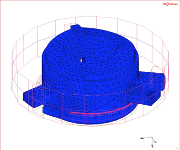
Figure 1: Typical four-noded tetrahedral mesh—overly stiff.
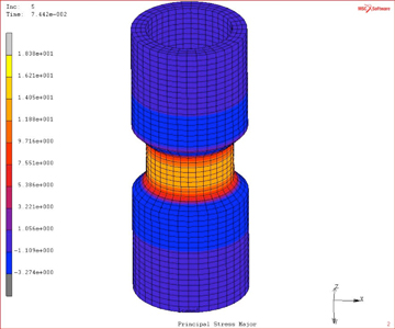
Figure 2: Hoop stress in molded PP component.
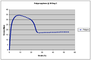
Figure 3: Typical polypropylene stress/strain curve. |
Along with these factors, a culture and associated lexicon began to develop wherein analysts largely bypassed the use of strain to describe the loading of a part or structure, and began to report results using stress quantities, such as Von Mises (average) stress. In linear analysis of metals in the elastic region, the terms are synonymous; stress and strain are nearly exactly proportional, so reporting one is as good as the other. It also makes sense if the total excursion as measured by strain is only 2%-3%. This is a small range, and stress outputs make a more finely divided measure as we go from zero stress to maybe 30,000 psi in a typical load case. So reporting stress makes good sense for metals.
Another consideration worth discussing is how FEA codes (all codes) work at the macro scale. No linear or nonlinear code actually measures stress. All FEA codes measure strains, or displacements in a Lagrangian mesh. Stress is a derived or computed quantity. The FE code applies a load to a mesh, and measures how much that mesh moves, and that’s it.
So stress is an indirect measure of part performance at best.
Beware linear codes
Moving away from the metals culture into plastics, now we have strains that are typically much, much larger than metals. Ultimate tensile strain can be upwards of 30%, and sometimes much more.
But we have FE codes that were designed to operate in the range of 2%-5% total strain. The basic kernels and displacement algorithms never anticipated very large displacements, and the types of elements and the computational underpinnings of high-strain problems do not translate well into codes that were designed for linear elastic analysis of metals.
So, even in a simple linear elastic analysis of plastics, we have to be careful that the exaggerated strains (as compared to steels) can be adequately managed with good accuracy. This goes to the computational techniques that are used by a given code, and within a given code it also goes to the element type, as the most common elements, such as four-noded tetrahedrals, inherently do not report large strains very accurately (they are artificially stiff—see Figure 1).
Now, many modern FE codes do, in fact, accommodate large strain formulations, but the analyst should not assume this is the case without benchmarking. As a practical aside, nonlinear codes do perform better here, even when doing linear elastic analysis, simply because the codes are designed to accommodate large deformations, and often have more robust element and material libraries that are much better suited to plastics analysis. Beware of using linear codes for plastics.
A simple early-stage benchmark that should be part of any organization seeking to perform structural analysis of plastics is to model an ASTM “dogbone” coupon in the computer, exactly as it would be set up in the Instron, and go to an outside lab to get a stress/strain curve of the plastic material to be benchmarked. Using the lab-generated materials data, the analyst should be able to get a good correlation between the computer model and the lab sample. A good nonlinear code with an elastic-plastic material model and high-quality elements should be able to match the analytical curve with the lab curve all the way to failure.
If this cannot be done with a high degree of accuracy on a test coupon, under no circumstances should FEA be attempted on a CAD part design with all its flow line dependencies and complexities. Crawl before you walk. An outside material test is only a few hundred dollars and well worth the effort. Many labs will mold the dogbones for you if you give them resin.
No strain, no gain
Because of the largely nonlinear coupling between stress and strain in plastics, the analyst should consider augmenting results using strain quantities in addition to stress. The stress quantities may be a complete fiction, but with a good code, the strains are likely to be pretty accurate.
Figure 2 is a color results plot showing a simple pressure vessel molded from polypropylene. The part shows a peak stress of 16 Mpa against a yield stress of 34 Mpa. Good design with plenty of safety factor, right?
Maybe not. A look at the stress/strain curve used for the material properties in this nonlinear analysis shows some surprises—namely, that there are many occurrences of the 16-Mpa stress threshold, and only one is before yield. All others indicate the part is in failure. So which 16-Mpa stress value are we looking at in Figure 2—before yield, or after? Using strain outputs in the results gives more definitive information on part performance. In this case, there is only one unique value for the applied load at 3% strain (Figure 3).
The field of nonlinear analysis of plastic parts is filled with complexity, but with the use of some basic principles and good practices, accurate analysis results can be had.
Techniques to get good results
• ?Benchmark materials often and early. Most organizations use less than a dozen or so resins, so it’s not a big deal to get material tests on any and all plastic resins before they are used in a part design.
• ?Validate that your solver and element mesh can accurately reproduce what the material coupons do in the lab—before you try a CAD part.
• ?Try to get used to reporting strains as well as stresses. There is more information in strains and less chance for error.
• ?Use high-quality elements. Four-noded tetrahedral, the mainstay of many FE codes, is artificially stiff when subjected to high deformations. Be careful using these low-quality elements and avoid them if possible.
• ?Do not rely on published properties. Always, repeat always, test your own material coupons and use the curves from the lab as input for your material properties.
• ?Make sure you understand the load direction of the part under analysis. Steels have similar elastic modulus, whether in tension, compression, or bending. Not so with plastics. For example, if you are anticipating a bending strain, make sure you get material properties for flexural strain because tensile properties will not help you and you’re likely to get an incorrect answer.
- What affects injection mold machining accuracy and productivity?
- Shenzhen top five mold manufacturers: how plastic products are processed and produced?
- Shenzhen Ideal Vowin mold manufacturer: how to effectively improve the precision of mold processing?
- Chrome plating, a process that makes cars stylish
- Six injection molding processing technologies for home appliance plastic products
- Advantages and disadvantages of injection molding vs blow molding
- What is automotive hot stamping and molding technology?
- What is the difference between a hot runner and a cold runner in the mold?
- Automotive stamping die in large, precision and other areas of progress is obvious, the rapid development of plastic and rubber molds
- The top ten problems that are likely to occur in the mold testing process