中文
ENGLISH
中文
ENGLISH
Q. We are molding long automotive parts that are to be chrome plated. These parts have long flow paths and require sequential valve gating to fill properly. But the parts often have surface marks that cause visible flaws after plating, resulting in high rates of expensive scrap. How do we fix this?—German automotive injection molder
 |
A. Sequential valve gating is a valuable technique for filling long parts that must meet cosmetic requirements. Typically, each nozzle opens after the melt flow front has passed, to avoid a weld line. Nevertheless, high injection pressures can result, due to the long flow lengths. All the closed nozzles are pressurized to the same degree, so that when the nozzle opens, the melt decompresses and “explodes” into the cavity like uncorked champagne, inducing extreme velocity peaks in the melt. This may leave surface marks and cause internal stresses and even material degradation.
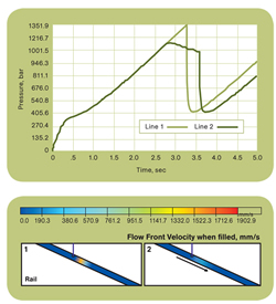
One solution to this problem is to apply a profiled injection rate shortly before and after the opening of the nozzle. We simulated your problem with our Cadmould 3D-F Fill and Cascadic Injection software. The accompanying figures show a comparison of the injection process with a constant injection flow rate (1) and with softly profiled filling (2) that temporarily reduces the flow rate to 25% of its maximum value. As you can see, the shear-rate and flow-front velocity peaks are lowered by about 70% using a “soft” velocity profile. The pressure loss at the switching point is reduced by 190 bar (2760 psi), improving the part quality significantly.
Harold Kutschera, head of Application Dept.
Simcon kunststofftechnische Software GmbH
Wuerselen, Germany
+49 2405 6450-0 • simcon-worldwide.com
Q. Lately I am noticing lines in the machine direction of my sheet. What could be the issue? —Midwest sheet extruder
A. The most likely cause is a dirty die. The die lip area is particularly susceptible to polymer buildup that will cause flow lines. The lips should be cleaned thoroughly with a soft tool (brass, copper, or wood). At the same time, the lips should be checked for any damage to their edges. Nicks or scratches in this area are very apt to cause MD flow lines and will need to be repaired. If neither of these areas is the source of the flow lines, the whole die should be split, cleaned, and inspected for damage. In most cases, these steps will eliminate MD flow lines that “only started recently.”


